Cannot Upload Sketch to Arduino Mega Cant
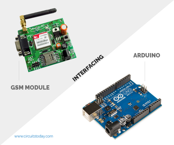
In this article, we are going to see how to interface the GSM Module with Arduino. In that location are dissimilar kinds of GSM modules available on the market. We are using the most popular module based on Simcom SIM900 and Arduino Uno for this tutorial. Interfacing a GSM module to Arduino is pretty simple. Yous only demand to make 3 connections betwixt the gsm module and Arduino. So let's become to business organisation!
A GSM Module is basically a GSM Modem (like SIM 900) connected to a PCB with unlike types of output taken from the board – say TTL Output (for Arduino, 8051 and other microcontrollers) and RS232 Output to interface straight with a PC (personal computer). The board will too accept pins or provisions to attach the mic and speaker, to have out +5V or other values of power and footing connections. These types of provisions vary with unlike modules.
Lots of varieties of GSM modems and GSM Modules are available in the market to choose from. For our project of connecting a gsm modem or module to Arduino and hence sending and receiving SMS using Arduino – it's always good to choose an Arduino compatible GSM Module – that is a GSM module with TTL Output provisions.
Do you like to do a beginners course on Arduino with 12+ Projects?
We have published an exciting course on Arduino named "Arduino Grade [Zero to Hero] – Learn By Doing Projects". The course is published in partnership with Udemy – the world's all-time online pedagogy platform. If you are looking to main Arduino and develop a couple of actually exciting projects using the Arduino platform, enrolling in this course would be the best determination you can brand to achieve your dreams. So let's take a quick look at what yous will learn in this course.
View Course Details
Our course "Arduino Course [Zilch to Hero]" follows a consummate learn past doing approach, where you will be learning each and every concept by doing a projection. The course is designed with 12+ projects ranging from easy, medium, and avant-garde projects. The course begins by introducing basic concepts and unproblematic led based projects, and then moves on to explain mid-level concepts similar sensor interfacing, sensor-based projects, and finally, the form teaches you how to do advanced projects and IoT (Net of Things) based projects using the Arduino platform.

Yous will practice the following projects in this full video form:
- Automatic Mitt Sanitizer/Soap Dispenser
- Automatic Light Control using LDR
- Generating Patterns with LEDs
- Smart Door Lock using Keypads (Digital Code Lock)
- Home Security System (Protect against Fire accidents, Gas leakage,)
- Weather Monitoring System (Mensurate Temperature & Humidity)
- Dwelling house Automation using Smartphone & TV Remote Control
- Line Follower Robot (the nuts to build robots)
- Obstacle Avoidance Robot (learn to build intelligence in robots)
- Mobile Phone controlled Robot Motorcar (wireless controlled robots)
- Smart Irrigation System
- IoT based Weather Station (Display weather data on website/web application)
View Course Details
Notes on GSM Module
1. We apply SIM900 GSM Module – This means the module supports communication in the 900MHz band. We are from India and most of the mobile network providers in this country operate in the 900Mhz band. If you are from some other country, you accept to bank check the mobile network ring in your area. A majority of Usa mobile networks operate in the 850Mhz ring (the ring is either 850Mhz or 1900Mhz). Canada operates primarily on the 1900 Mhz band. Please read this wiki entry on GSM Frequency Bands around the World .
2. Cheque the power requirements of the GSM module – GSM modules are manufactured by different companies. They all accept different input ability supply specs. You demand to double-cheque your GSM module's power requirements. In this tutorial, our gsm module requires a 12 volts input. So we feed it using a 12V,1A DC power supply. I have seen gsm modules that require 15 volts and another types which demand but 5 volts input. They differ with manufacturers. If yous are having a 5V module, you tin can power it directly from Arduino's 5V out.
Note:- GSM Modules are manufactured past connecting a particular GSM modem to a PCB and then giving provisions for RS232 outputs, TTL outputs, Mic and Speaker interfacing provisions etc. The virtually popular modem under use is SIM 900 gsm modem from the manufacturer SIMCom. They besides manufacture GSM Modems in bands 850, 300 and other frequency bands.
three. Check for TTL Output Pins in the module – Y'all can feed the data from the gsm module directly to Arduino merely if the module is enabled with TTL output pins. Otherwise, you take to convert the RS232 data to TTL using MAX232 IC and feed information technology to Arduino. Most of the gsm modules on market are equipped with TTL output pins. Merely ensure you are buying the right one.
So that'southward all about the gsm module basics. Now let'due south power it up!

GSM Module – Buyers Guide – are you looking to purchase a GSM module? There are a scattering of product variants for GSM module – like SIM900, SIM300, SIM800 etc. We have created this buyers guide to help you select the right GSM module for your project needs.
Booting the GSM Module!
one. Insert the SIM card into the GSM module and lock it.
2. Connect the adapter to the GSM module and turn it ON!
3. Now await for some time (say ane minute) and see the blinking rate of 'condition LED' or 'network LED' (GSM module volition take some fourth dimension to plant a connectedness with mobile network)
four. Once the connexion is established successfully, the condition/network LED volition blink continuously every three seconds. You lot may endeavour making a call to the mobile number of the sim card within the GSM module. If y'all hear a ring back, the gsm module has successfully established a network connection.
Okay! Now permit's encounter how to connect a gsm module to Arduino!
Connecting GSM Module to Arduino
In that location are 2 ways of connecting the GSM module to Arduino. In any example, the communication between Arduino and GSM modules is series.
1. Without SoftwareSerial Library
two. With SoftwareSerial Library
Method 1
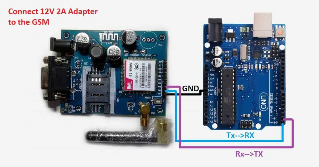
If you are going with the first method, you have to connect the Tx pin of the GSM module to the Rx pin of Arduino and the Rx pivot of the GSM module to the Tx pin of Arduino. You read information technology right? GSM Tx –> Arduino Rx and GSM Rx –> Arduino Tx.
Now connect the ground pin of Arduino to the ground pin of the gsm module!
So that'due south all! Y'all made all three connections and the wiring is over! Now you can load different programs to communicate with the gsm module and brand it piece of work.
Note:- The problem with this connection is that, while programming Arduino uses series ports to load programs from the Arduino IDE. If these pins are used in wiring, the plan will not be loaded successfully to Arduino. So you accept to disconnect wiring in Rx and Tx each time you lot burn down the program to Arduino. One time the program is loaded successfully, you tin can reconnect these pins and have the organisation working!
Circuit diagram of interfacing GSM module with Arduino(without using the library)

Arduino code for Circuit diagram of interfacing GSM module with Arduino(without using the library)
void setup() { Series.begin(9600); filibuster(100); } void loop() { if (Serial.available()>0) switch(Series.read()) { case 's': SendMessage(); break; case 'r': RecieveMessage(); intermission; } if (mySerial.available()>0) Serial.write(mySerial.read()); } void SendMessage() { mySerial.println("AT+CMGF=1"); //Sets the GSM Module in Text Mode filibuster(1000); // Delay of 1000 milli seconds or one second mySerial.println("AT+CMGS=\"+91xxxxxxxxxx\"\r"); // Replace ten with mobile number filibuster(1000); mySerial.println("I am SMS from GSM Module");// The SMS text you lot desire to send delay(100); mySerial.println((char)26);// ASCII code of CTRL+Z filibuster(1000); } void RecieveMessage() { mySerial.println("AT+CNMI=two,2,0,0,0"); // AT Command to receive a live SMS delay(grand); } Method ii
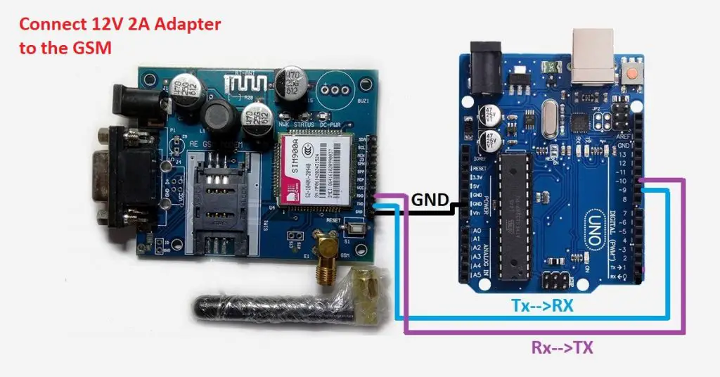
To avert the difficulty mentioned above, I am using an alternating method in which two digital pins of Arduino are used for serial communication. We need to select two PWM enabled pins of Arduino for this method. So I choose pins 9 and ten (which are PWM enabled pins). This method is made possible with the SoftwareSerial Library of Ardunio. SoftwareSerial is a library of Arduino which enables serial data communication through other digital pins of Arduino. The library replicates hardware functions and handles the task of series communication.
I hope y'all understood so far! Let's go to the circuit diagram! So given below is the excursion diagram to connect the gsm module to Arduino – and hence use the circuit to ship SMS and receive SMS using Arduino and gsm modem.
Circuit diagram of interfacing GSM module with Arduino(without library)

Arduino code for Circuit diagram of interfacing GSM module with Arduino(with using the library)
#include <SoftwareSerial.h> SoftwareSerial mySerial(nine, 10); void setup() { mySerial.begin(9600); // Setting the baud rate of GSM Module Serial.brainstorm(9600); // Setting the baud rate of Serial Monitor (Arduino) delay(100); } void loop() { if (Series.available()>0) switch(Serial.read()) { case 'southward': SendMessage(); break; case 'r': RecieveMessage(); break; } if (mySerial.bachelor()>0) Serial.write(mySerial.read()); } void SendMessage() { mySerial.println("AT+CMGF=1"); //Sets the GSM Module in Text Mode filibuster(1000); // Delay of m milli seconds or 1 2nd mySerial.println("AT+CMGS=\"+91xxxxxxxxxx\"\r"); // Replace x with mobile number delay(1000); mySerial.println("I am SMS from GSM Module");// The SMS text yous want to send delay(100); mySerial.println((char)26);// ASCII code of CTRL+Z delay(thou); } void RecieveMessage() { mySerial.println("AT+CNMI=2,ii,0,0,0"); // AT Control to receive a alive SMS delay(thousand); } The program has two objectives as described below:-
1) Ship SMS using Arduino and GSM Module – to a specified mobile number inside the program
2) Receive SMS using Arduino and GSM Module – to the SIM bill of fare loaded in the GSM Module.
so that'southward the program/code to make Arduino ship SMS and receive SMS using the gsm module! Let'south get to the explanation of the program!
The Program Explanation
We begin by including the SoftwareSerial library into the programme. In the next line, we create a constructor of SoftwareSerial with the name mySerial and we pass the digital pin numbers as parameters. The bodily format is similar SoftwareSerial mySerial (Rx, Tx);
So in our code, pin number 9 will act every bit Rx of Arduino and 10 volition human action equally Tx of Arduino. Let's get to the configuration office of the program inside setup. The showtime task is to set baud rates of the SoftwareSerial library to communicate with the GSM module. We achieve this by invoking mySerial.begin part. Our second job is to set the baud rate of Arduino IDE's Serial Monitor. Nosotros do this by invoking the Series. brainstorm() function. Both should be set at the same baud charge per unit and we use 9600 bits/second here in our tutorial. The configuration role is over with setting baud rates and it's expert to requite a small filibuster of 100 milliseconds.
Now let's get to the actual program inside the loop(). To make things simpler, I accept developed a user input based plan. The program seeks user input via the series monitor of Arduino. If the input is 'southward' the program volition invoke a function to send an SMS from the GSM module. If the user input is 'r', the programme will invoke the function to receive a live SMS from the GSM module and brandish information technology on the serial monitor of Arduino. The whole program is as elementary as that!
Series. bachelor() – checks for any data coming through the serial port of Arduino. The function returns the number of bytes available to read from the serial buffer. If there is no data available, it returns a -1 (value less than zero).
Series. read() – Reads all the data bachelor on series buffer (or incoming serial data if put otherwise). Returns the offset byte of incoming series data.
mySerial.bachelor() – checks for any data coming from the GSM module through the SoftwareSerial pins 9 and 10. Returns the number of bytes available to read from the software series port. Returns a -1 if no data is available to read.
mySerial.read() – Reads the incoming data through a software serial port.
Serial.write() – Prints data to series monitor of arduino. So the role Serial.write(mySerial.read()) – prints the data collected from software serial port to serial monitor of arduino.
Lets go the functions SendMessage() and RecieveMessage()
These are the functions in which we actually ship commands to the GSM module from Arduino. These commands to communicate with the GSM module are called AT Commands. There are unlike commands to perform different tasks using the GSM module. Y'all tin read the consummate AT Commands Library to understand all that is possible with the GSM module.
SendMessage() – is the function we created in our Arduino sketch to send an SMS. To send an SMS, we should set our GSM module to Text style first. This is accomplished past sending an AT Command "AT+CMGF=1" Nosotros send this control by writing this to the SoftwareSerial port. To reach this we use the mySerial.println() function. mySerial.println writes data to the software serial port (the Tx pin of our Software Serial – that is pin x) and this will be captured by the GSM module (through its Rx pin). After setting the GSM module to Text mode, we should the mobile number to which nosotros shall ship the SMS. This is achieved with AT command "AT+CMGS=\"+91xxxxxxxxxx\"\r" – where you lot may replace all x with the mobile number.
In the next step, we should send the actual content of the SMS. The end of SMS content is identified with the CTRL+Z symbol. The ASCII value of this CTRL+Z is 26. So nosotros send a char(26) to the GSM module using the line mySerial.println((char)26); Each and every AT command may exist followed by a one-second delay. We must give some fourth dimension for the GSM module to respond properly. Once these commands are sent to the GSM module, y'all shall receive an SMS in the ready mobile number.
RecieveMessage() – is the function to receive an SMS (a live SMS). The AT command to receive a live SMS is "AT+CNMI=2,2,0,0,0" – we but demand to send this command to the GSM module and apply a one-2d delay. Once you lot send this command, try sending an SMS to the SIM card number put inside the GSM module. You will run across the SMS you had sent displayed on your Arduino series monitor.
There are different AT commands for unlike tasks. If you desire to read all SMSs stored in your SIM bill of fare, send the following AT Control to the gsm module – "AT+CMGL=\"ALL\"\r"
Okay! That'south all and you are done. And you have learnt how to employ Arduino to transport SMS and receive SMS messages with an example code.
I shall summarize this tutorial on how to send/receive a text message using Arduino and gsm module with the post-obit notes:-
AT Commands to Send SMS using Arduino and GSM Module
AT+CMGF=1 // Set the GSM module in text way AT+CMGS=\"+YYxxxxxxxxxx\"\r // Input the mobile number| YY is land code "the bulletin" with stopping character (char)26 // ASCII of ctrl+z
AT Commands to Receive SMS using Arduino and GSM Module
AT+CMGF=1 // Ready the GSM Module in text manner AT+CNMI=two,2,0,0,0 // AT Control to receive live sms
Read the AT commands library and start playing with your GSM module and Arduino! If you have any doubts please enquire in the comments.
So that'southward all almost interfacing the GSM module with Arduino. If you've whatsoever doubts, feel gratuitous to comment.
Source: https://www.circuitstoday.com/interface-gsm-module-with-arduino
0 Response to "Cannot Upload Sketch to Arduino Mega Cant"
Post a Comment